The Rename Stage
The Rename stage maps the ISA (or logical) register specifiers of each instruction to physical register specifiers.
The Purpose of Renaming
Renaming is a technique to rename the ISA (or logical) register specifiers in an instruction by mapping them to a new space of physical registers. The goal to register renaming is to break the output-dependencies (WAW) and anti-dependences (WAR) between instructions, leaving only the true dependences (RAW). Said again, but in architectural terminology, register renaming eliminates write-after-write (WAW) and write-after-read (WAR) hazards, which are artifacts introduced by a) only having a limited number of ISA registers to use as specifiers and b) loops, which by their very nature will use the same register specifiers on every loop iteration.
The Explicit Renaming Design
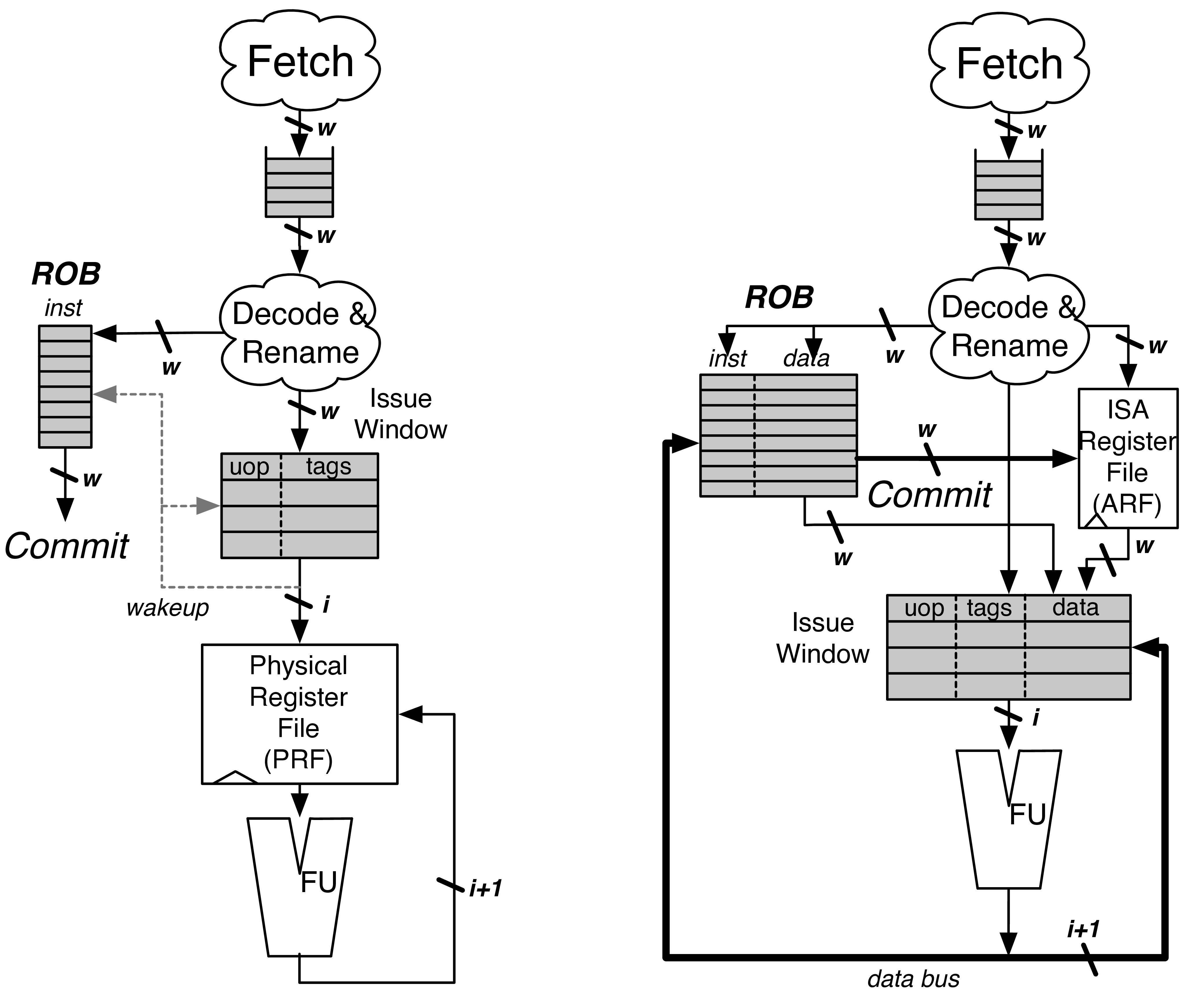
Fig. 14 A PRF design (left) and a data-in-ROB design (right)
BOOM is an “explicit renaming” or “physical register file” out-of-order core design. A Physical Register File, containing many more registers than the ISA dictates, holds both the committed architectural register state and speculative register state. The Rename Map Table s contain the information needed to recover the committed state. As instructions are renamed, their register specifiers are explicitly updated to point to physical registers located in the Physical Register File. [1]
This is in contrast to an “implicit renaming” or “data-in-ROB” out-of-order core design. The Architectural Register File (ARF) only holds the committed register state, while the ROB holds the speculative write-back data. On commit, the ROB transfers the speculative data to the ARF[2]_
The Rename Map Table
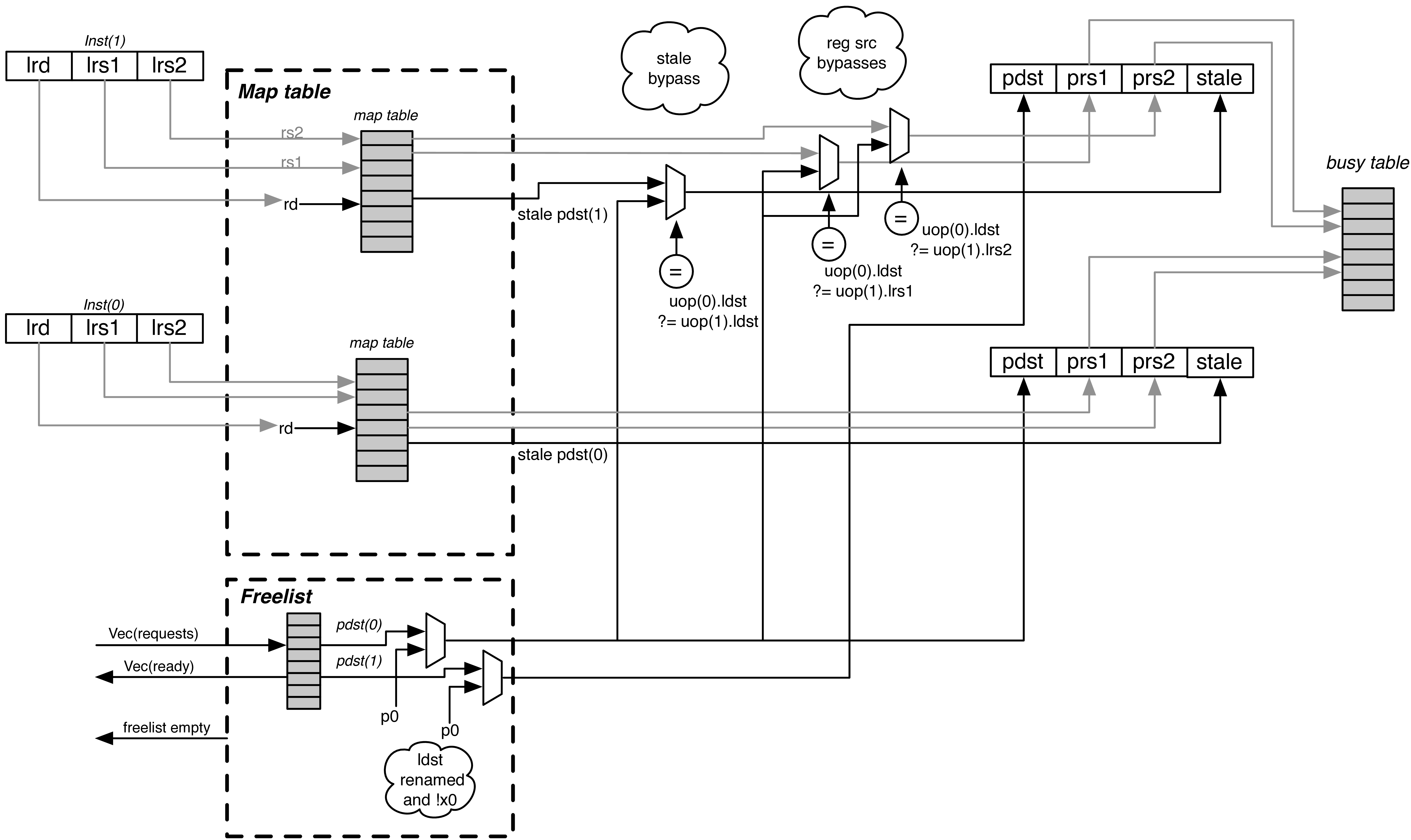
Fig. 15 The Rename Stage. Logical register specifiers read the Rename Map Table to get their physical specifier. For superscalar rename, any changes to the Map Tables must be bypassed to dependent instructions. The physical source specifiers can then read the Busy Table. The Stale specifier is used to track which physical register will be freed when the instruction later commits. P0 in the Physical Register File is always 0.
The Rename Map Table (abbreviated as Map Table) holds the speculative mappings from ISA registers to physical registers.
Each branch gets its own copy of the Rename Map Table[3]_ On a branch mispredict, the Rename Map Table can be reset instantly from the mispredicting branch’s copy of the Rename Map Table
As the RV64G ISA uses fixed locations of the register specifiers (and no implicit register specifiers), the Map Table can be read before the instruction is decoded! And hence the Decode and Rename stages can be combined.
Resets on Exceptions and Flushes
An additional, optional “Committed Map Table” holds the rename map for the committed architectural state. If enabled, this allows single-cycle reset of the pipeline during flushes and exceptions (the current map table is reset to the Committed Map Table). Otherwise, pipeline flushes require multiple cycles to “unwind” the ROB to write back in the rename state at the commit point, one ROB row per cycle.
The Busy Table
The Busy Table tracks the readiness status of each physical register. If all physical operands are ready, the instruction will be ready to be issued.
The Free List
The Free List tracks the physical registers that are currently un-used and is used to allocate new physical registers to instructions passing through the Rename stage.
The Free List is implemented as a bit-vector. A priority decoder can then be used to find the first free register. BOOM uses a cascading priority decoder to allocate multiple registers per cycle. [4]
On every branch (or JALR), the Rename Map Tables are snapshotted to allow single-cycle recovery on a branch misprediction. Likewise, the Free List also sets aside a new “Allocation List”, initialized to zero. As new physical registers are allocated, the Allocation List for each branch is updated to track all of the physical registers that have been allocated after the branch. If a misspeculation occurs, its Allocation List is added back to the Free List by OR’ing the branch’s Allocation List with the Free List. [5]
Stale Destination Specifiers
For instructions that will write a register, the Map Table is read to get the stale physical destination specifier (“stale pdst”). Once the instruction commits, the stale pdst is returned to the Free List, as no future instructions will read it.
| [1] | The MIPS R10k, Alpha 21264, Intel Sandy Bridge, and ARM Cortex A15 cores are all example of explicit renaming out-of-order cores. |
| [2] | The Pentium 4 and the ARM Cortex A57 are examples of implicit renaming designs. |
| [3] | An alternate design for wider pipelines may prefer to only make up to one snapshot per cycle, but this comes with additional complexity to deduce the precise mappings for any given instruction within the Fetch Packet. |
| [4] | A two-wide Rename stage could use two priority decoders starting from opposite ends. |
| [5] | Conceptually, branches are often described as “snapshotting” the Free List (along with an OR’ing with the current Free List at the time of the misprediction). However, snapshotting fails to account for physical registers that were allocated when the snapshot occurs, then become freed, then becomes re-allocated before the branch mispredict is detected. In this scenario, the physical register gets leaked, as neither the snapshot nor the current Free List know that it had been freed. Eventually, the processor slows as it struggles to maintain enough inflight physical registers, until finally the machine comes to a halt. If this sounds autobiographical because the original author (Chris) may have trusted computer architecture lectures, well… |